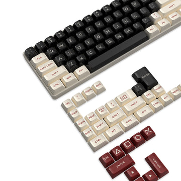



A 3-pin switch generally fits any hot-swap PCB built for 5-pin switches, because it only needs its two metal contact pins and center plastic post to line up with the board. A 5-pin switch needs those same contacts plus two outer plastic legs, so it only drops into a PCB that has all four matching holes unless those legs are removed first. Socket brand names like Outemu, Kailh, or Gateron do not replace checking the exact PCB and switch you actually own before you install anything.
3-Pin vs 5-Pin: The Compatibility Rule
The deciding factor is whether your PCB's holes match your switch's pins and legs, not the name printed on the socket. Extra holes on a 5-pin-compatible PCB never block a 3-pin switch, but missing holes will stop an unmodified 5-pin switch from seating correctly.
| Switch configuration | PCB requirement | Reader decision |
|---|---|---|
| 3-pin switch on a 5-pin-compatible PCB | Needs only the 2 contact holes and center post hole | Install directly; the unused leg holes don't matter |
| 3-pin switch on a 3-pin-only PCB | Needs only the 2 contact holes and center post hole | Install directly |
| 5-pin switch on a 3-pin-only PCB | Needs 2 more holes for the outer legs, which aren't present | Choose a 3-pin switch, use a 5-pin PCB, or clip the legs only after confirming fit |
In practice, 3-pin switches are the flexible choice, while 5-pin switches are the ones that need a fit check before you buy. If you're weighing the cheapest mechanical keyboard with hot-swap support against a pricier one, this hole pattern matters more than the switch brand name on the box.
What the Three and Five Pins Actually Do
Not every pin on a switch does the same job. Two of them carry an electrical signal, and the rest exist purely to hold the switch in place while it's pressed.
Metal contact pins versus plastic locating features
Every hot-swappable switch has two metal pins on its underside. These are the only parts that carry electrical signal into the socket, and they're what actually registers a keypress. The center plastic post found on most switches, plus the two additional plastic legs on a standard 5-pin switch, are physical locating features. They keep the switch square and centered while it's pressed into the board, but they don't touch any electrical contact. That distinction matters because a bent metal pin can stop a switch from working even when every plastic feature lines up perfectly.
What the plate and PCB each contribute
A mounting plate supports the switch from above and helps it sit level, but the plate itself doesn't decide compatibility. That decision belongs to the PCB, since its hole pattern determines whether the switch's metal pins and plastic legs can pass through cleanly. This is why a PCB drilled for 5-pin switches doesn't make 3-pin switches unusable: the extra holes for the outer legs simply go unused when a 3-pin switch is installed, and the two contact pins still land in the same spots either way.
Check the PCB Hole Pattern Before Installing a Switch
Confirm compatibility by looking at the bare board, not the switch's housing or the keycap. The socket orientation and hole spacing on your exact PCB are what decide whether a switch will seat cleanly.

Start with the PCB, not the socket label
Locate your board's switch footprint and note which way the socket is oriented. You should be able to spot the two small openings for the metal contact pins, a slightly larger center opening for the plastic post, and, if the board supports 5-pin switches, two additional round openings positioned outside the center post for the plastic legs. If you only see the center and two contact holes, the board is built for 3-pin switches only.
Confirm the switch profile and underside
Before buying or installing, work through this quick check:
- Confirm the switch is a standard MX-style mechanical switch rather than a low-profile, optical, or magnetic design, since those use different footprints entirely.
- Look at the pins from underneath and confirm they're straight and evenly spaced, not bent toward one side.
- When the layout still isn't obvious, check your board's documentation or the switch manufacturer's page for the exact footprint instead of guessing from photos.
Outemu, Kailh, and Gateron-Style Sockets: What Is Actually Comparable?
Socket names like Outemu, Kailh, and Gateron describe families of hot-swap sockets, not one fixed design with guaranteed compatibility or durability. The documentation available for specific models shows narrow, part-level facts rather than a brand-wide ranking.
| Documented part | Evidence scope | What it does and doesn't establish |
|---|---|---|
| Outemu-style hot-swap socket | Compatibility notes tied to one documented implementation | Shows that implementation's fit boundary; doesn't cover every Outemu-labeled socket |
| Kailh New MX Hot Swap Socket CPG151101S11 | Listed with a 5,000-cycle operating-life spec for this model | A named-part spec only; not a lifespan promise for other Kailh-style sockets |
| Gateron low-profile Switch Hot-swap PCB 2.0 Socket | Documentation covers a low-profile socket design | Confirms low-profile compatibility only, not standard MX-style 3-pin/5-pin fit |
None of these entries supports a universal winner across the three brand styles. The safer approach is matching your exact socket and switch model against its own documentation instead of assuming a brand name guarantees fit or lifespan.
Install a Switch Without Bending Its Pins
Work through the board and switch in this order so you catch a misalignment before it becomes a bent pin or a stressed socket.
- Power down the keyboard and expose the PCB by removing the keycap and, if needed, the plate over that switch position.
- Identify the socket's footprint and orientation so you know which way the switch needs to face.
- Flip the new switch over and inspect its two metal pins for straightness before it ever touches the board.
- Gently correct any minor pin misalignment by hand; never force a bent pin into the socket.
- Line up the switch's contact pins, center post, and any outer legs with their matching holes.
- Press down with light, even pressure until the switch clicks into place, using a switch puller tool if you need better grip and control during removal or reseating.
- Test the key once it's seated, and if it doesn't register or feels uneven, pull the switch back out and recheck pin alignment before trying again.
If the switch resists at step 6 instead of seating smoothly, stop pressing. Remove it, recheck the pins and holes, and correct the alignment before you try again; pushing harder is what bends pins and stresses solder pads.
Should You Clip the Plastic Legs?
Clip the plastic legs only when a 5-pin switch needs to go into a PCB that doesn't have the matching outer holes, and only after you've confirmed everything else fits.
- Leave the legs intact when your PCB already has all four holes for a 5-pin switch, or when you're using a 3-pin switch that doesn't have legs to begin with.
- Consider clipping only after you've confirmed the board is a 3-pin-only PCB, the switch's electrical pin spacing and profile are otherwise standard MX-compatible, and you accept that clipping is irreversible.
Clipping solves physical interference from missing leg holes. It does nothing to fix mismatched pin spacing or a switch profile that was never going to fit that board, so verify those two things first rather than reaching for cutters as a first step.
Protect the Hot-Swap Socket and PCB During Removal
Socket durability comes down to handling, not a fixed number of swaps stamped on any one product. Keeping switches aligned and removing them carefully matters more than any single spec.
Handling habits that reduce socket stress
Keep the switch straight and use controlled, even pressure both when installing and removing it. If a switch resists removal, pulling at an angle or repeatedly reseating it without fixing the underlying mismatch is what stresses the solder joints, not a single careful swap. Our ATTACK SHARK K86 hot-swap keyboard lists its sockets for up to 10,000 switch swaps, but that figure is specific to the K86's own socket design and switch spacing, not a promise that applies to every hot-swap board.
Signs to stop and inspect the PCB
Watch for these three signs and stop handling the board yourself if you see them:
- The socket moves or visibly separates from the PCB when you insert or remove a switch.
- The solder area around the socket looks lifted, cracked, or discolored.
- A correctly aligned, straight-pinned switch still doesn't register a keypress after reinstalling it.
Any of these point to a socket or solder issue rather than a switch problem, and that's a case for board documentation or repair support rather than another reseat attempt.

What to Do When the Fit Is Uncertain
Stop pressing the switch in if you're not sure it fits, and write down two things: your exact PCB or socket model, and your exact switch model or profile. Guessing from an Outemu, Kailh, or Gateron label isn't a substitute for that documentation, since the evidence behind those names covers specific parts, not every socket sold under the brand.
Once you have both model names, compare them against the manufacturer's own documentation or reach out to support before you clip a leg, buy a replacement, or push a switch in with extra force. A mismatch in pin spacing or switch profile needs a different part, not more pressure.
FAQs
Does the 3-pin versus 5-pin rule apply to low-profile, optical, or magnetic switches?
Standard 3-pin and 5-pin compatibility guidelines apply specifically to standard MX-style mechanical switches. Low-profile, optical, and magnetic switch systems feature proprietary pin spacing, sensor cutouts, or non-MX socket geometry. Always consult the exact board and switch specifications for non-standard formats rather than relying on standard MX hole patterns.
Can clipping the plastic legs ruin a 5-pin switch?
Clipping the two outer plastic alignment pins does not harm electrical conductivity because only the two metal pins carry signals. However, removing them is completely irreversible and reduces structural alignment on plateless builds, so only clip them when installing into a verified 3-pin-only PCB with a mounting plate.
What should you do if a switch pin bends during installation?
Stop applying downward force immediately and pull the switch straight out. Inspect the bent copper leg and gently straighten it using precision tweezers or your fingers before checking the PCB socket hole for obstruction, re-aligning carefully, and testing again with light, even pressure.